2020
Functionalization and characterization protocol;
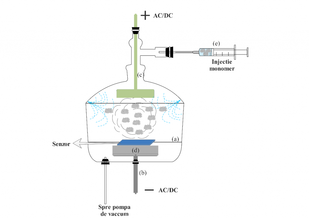
a) Plasma polymerization technique. An internal electrode reactor plasma polymerization system was used. The electric shock can be alternating current, direct current or radio frequency. The configuration of the plasma polymer synthesis reactor (figure below) consists of the reaction chamber (a), fixed cylindrical cathode (b), mobile anode (c), sample holder (d), monomer purge system (e) , vacuum pump and direct current source.
b) Physical or chemical immobilization technique. The sensors will be prepared by immobilizing the metallo-porphyrins on the carbon support of a sensor. Metal-porphyrins will be immobilized by both the physical method – drop cast and chemical – the covalent binding of porphyrins to the substrate. The physical method involves dissolving 1 mg of metallo-porphyrin in 1 mL of the appropriate solvent (chloroform) and dripping 5 μL of the solution onto the sensor. After drying the solvent, the sensor will be washed with distilled water to remove excess reactants and then dried in an oven. The chemical method involves oxidizing the carbon support in oxygen plasma (the auxiliary and reference electrodes, as well as the contacts will be covered) for 1 minute to attach the oxygen functional groups, the next step being the chlorination using a 20% SOCl2 solution, heated to 60 0C. This process allows the chlorination of the support surface and, implicitly, the facilitation of the covalent bonding of porphyrin to the carbon support. 5 μL of 1 mg / mL metallo-porphyrin solution will be dropped and allowed to react for 30 minutes. The process will be repeated 3 times to ensure an excess of reactants on the surface of the working electrode. After drying, the sensor will be washed with distilled water to remove all impurities.
c) Electropolymerization technique. A potentiostat consisting of a typical electrochemical cell, a working electrode (sensor), a reference electrode (SCE saturated calomel) and an auxiliary electrode (steel plate, with an area of 6.25 cm2) are used. Sample 1: The polymerization solution consists of a supporting electrolyte, 0.1 M HClO4, in which 1 mg GOx (graphene oxide – prepared in the laboratory) or G-Cl (chlorinated graphene – prepared in the laboratory) and 0.144 M pyrrole monomer are dispersed by ultrasound. The solution will be transferred to the electrochemical cell and the potential will be scanned between 800 mV → -1175 mV, with a scanning speed of 100 mV / s. Sample 2: The polymerization solution will be made by dispersing 5 mg of graphene and 500 µL aniline monomer in 25 mL H2SO4 1 M. For polymerization and deposition of the sensitive layer on the sensor, the potential between -200 mV and 1250 mV vs SCE will be swept, for 10 cycles.
2021
Electrical circuit design protocol;
Wiring diagram, power supply + 5V (Gas sensor), power supply + 3.3V Wi-Fi module ESP8266, gas sensor digital signal connections.
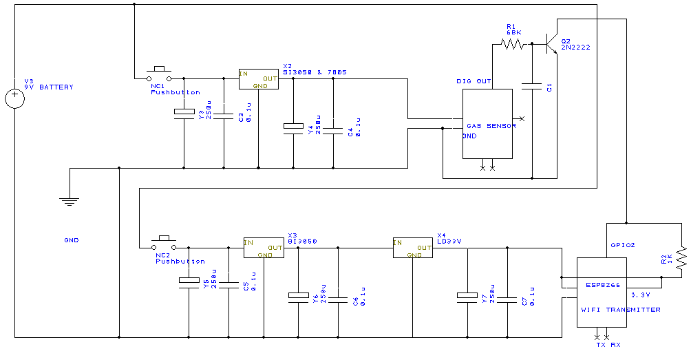
Functionalized graphene fabrication protocol; Modified graphenes characterization protocol; Gas sensor fabrication protocol; Gas sensor characterization protocol; Sensitive array fabrication protocol are interconnected and presented below.
1. Electropolymerization of conductive-graphene polymers on ceramic and plastic support (PET)
The electropolymerization was performed as follows: 1 mg of nanopelets graphene was dispersed in a solution containing 10% conductive polymer (aniline / pyrrole) in 0.1 M HClO4 using the ultrasonic processor at 45% amplitude and 750 W for 170 s. As agglomeration was found in the solution, the conductive graphene-polymer solution was centrifuged for 5 minutes at 4000 RPM. The deposit was removed, keeping only the supernatant (figure below). It was transferred to the electrochemical cell in which three electrodes were inserted: the saturated calomel electrode (with the function of reference electrode), the Pt electrode (with the function of auxiliary electrode) and the interdigitized electrodes (used as working electrode). Cyclic voltammetry was performed on an OrigaFlex 500 system. The potential was scanned between -750 mV and 750 mV (for pyrrole electropolymerization) and -800 mV and 800 mV (for aniline electropolymerization), with a speed of 200 mV / s and a 1: 7 sampling rate.
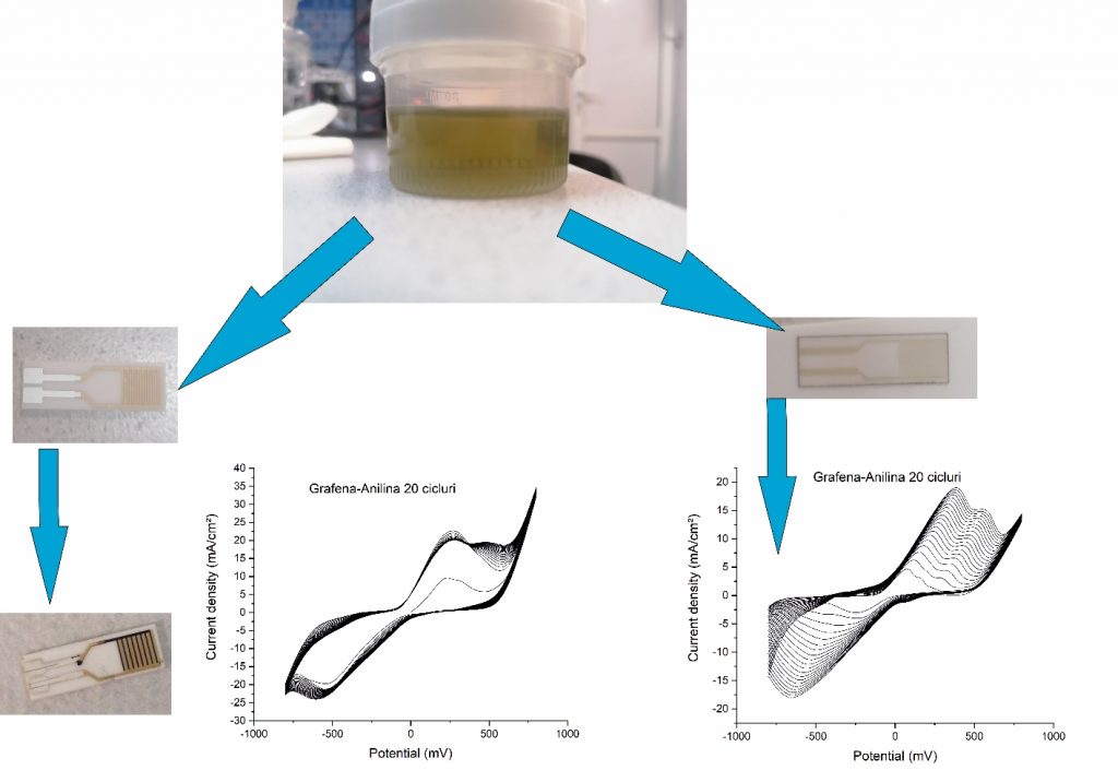

Electropolymerization results for the graphene-polyaniline sensitive system for: a) 10 cycles; b) 20 cycles; c) 30 cycles; d) 100 cycles and e) SEM topography (100 cycles)
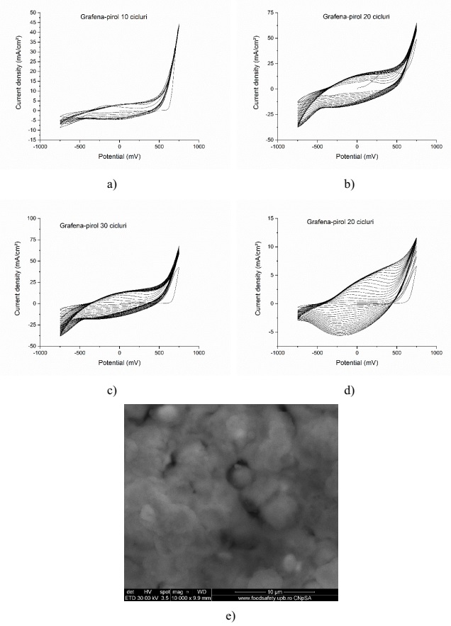
Graphene-pyrrole on interdigitized ceramic support: a) electropolymerization 10 cycles; b) 20 cycles; c) 30 cycles; d) electropolymerization on interdigitized plastic support; e) SEM topography for the electropolymerized graphene-pyrrole system on interdigitized ceramic support (30 cycles);
2. Electropolymerization of the graphene-pyrrole system on LSG interdigitized electrodes
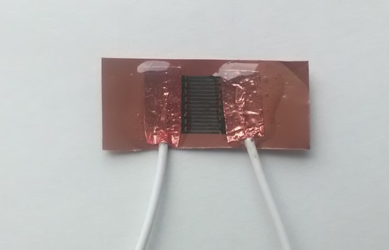
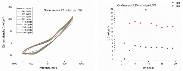
The replacement of interdigitized electrodes on plastic and ceramic support with LSG (laser scribed graphene) interdigitized electrodes has a different electrochemical characteristic than the one observed so far. Thus, for the electropolymerization of the graphene-pyrrole system on LSG it is observed the appearance of a very high current density (approximately 250 mA / cm2) and the saturation of the electrode surface after only 5 cycles (figure below), characteristics observed for both anodic and cathodic current.
3. Plasma polymerization of aniline-graphene nanocomposites on screen printing sensors
Graphene-polyaniline sensors were prepared by plasma polymerization on the working electrode of a screen printing sensor. It was started from two precursors, graphene, respectively the aniline monomer, obtained by distilling the aniline solution. The precursors (2 mg graphene and 5 mL aniline, 98%) were dispersed with ultrasound for 30 min. The sensor was covered with a mask that leaves only the interdigits area free; this area was cleaned with oxygen plasma for 1 minute before being subjected to the composite modification process. The plasma polymerization process took place using a carrier gas (Ar), which “transported” the monomer-graphene mixture solution to the plasma chamber, initiating the polymerization of aniline and its deposition with graphene on the interdigits of the sensor. At the end of the curing process, the modified sensor was washed several times with distilled water and dried at room temperature.
Electrical circuit fabrication protocol;
To achieve the sensor area and its integration with the electrical circuit, a prototype was developed (figure below) which replaces the sensor area with 2 commercial gas sensors (CO2 and NH3) in order to establish the optimal geometry of the sensor area and the characteristics to fulfill this.

2022
Experimental model :

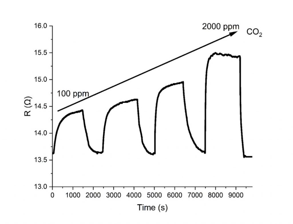
The response of the graphene-polyaniline sensors developed within this project to the time variation of the CO2 level.

The response of the graphene-polypyrrole sensors developed within this project to the time variation of the NH3 level.
